No relevant results
How to Fix iPhone 11 Pro Max Face ID Not Available - Motherboard Repair
May 06, 2022
As we all know, iPhone X and later models can easily come with Face ID failure after being dropped or water damaged. However, it should also be noted that improper operation during daily repair might also bring damage to Face ID relevant components and therefore result in Face ID not working failure. Today REWA LAB will show you how to repair iPhone 11 Pro Max Face ID issues.
Problem
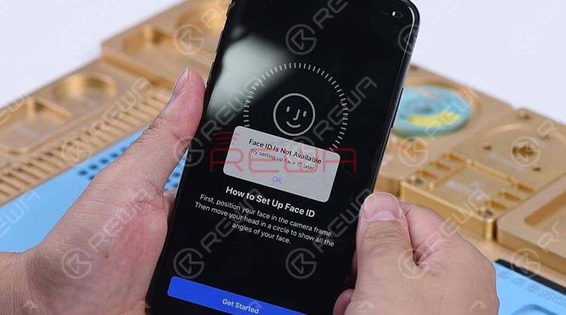
When trying to set up Face ID on the iPhone, we get the message 'Face ID is Not Available, try setting up Face ID later'. Start the Camera app and select Portrait in the bottom bar, then switch to the front camera. When the camera detects a person's face, the name of the lighting effect ‘Natural Light’ stays the same and there is also no flashing red light from the Dot Projector.
Diagnosis
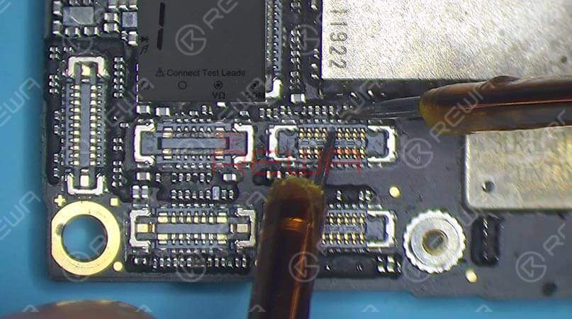
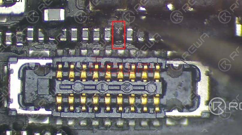
Let's check the Face ID parts first. We found the earpiece speaker and sensor flex cable are normal. The dot projector flex cable, the infrared camera flex cable, and the front camera flex cable also haven’t been damaged. The next step we should check the motherboard. Run diode mode measurement of the earpiece speaker and sensor connector, and the dot projector connector. The measured value is normal. Continue measuring the infrared camera connector. Judging by the measured value, the Pin 8 relevant circuit has open-circuited. The normal value should be 260 or so. Outputted from PMU, the 1.8V voltage reaches Pin 8 of the infrared camera connector by way of the inductor circled in red on the bitmap. Next, we just need to check the relevant components of the rail. We found the inductor is damaged. Our initial judgment is that when replacing the screen, the improper operation of our client during flex cable disconnecting accidentally damaged the inductor.
Troubleshooting
Remove black adhesive around the inductor firstly. Apply some medium-temp solder paste to the bonding pad. Then, tin the bonding pad with solder paste with the help of the Soldering Iron at 365℃. Once done, clean with PCB Cleaner. Continue to apply some rosin to the bonding pad and get a zero-ohm resistor in the right position. Solder with Hot Air Gun, then Clean with PCB Cleaner afterward. Run diode mode measurement of Pin 8 on the infrared camera connector. The measured value is 257, which is normal.
Reassemble and Test
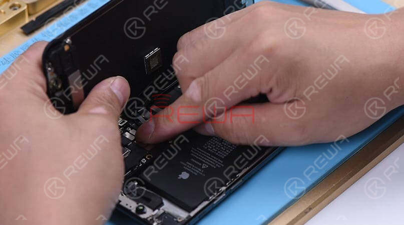
Get the logic board assembled and buckle the display assembly. The name of the lighting effect ‘Natural Light’ turns yellow when the camera detects a person's face. There is also a flashing red light from the Dot Projector. Next, continue to set up Face ID. Fault cleared.
Tools Used
Soldering Station & Material Set
Medium-Temperature Solder Paste
Visit our online shop for more parts and tools.You can also visit REWA YouTube Channel to check our video.
 REFOX
REFOX
 Other Parts


Write a comment